Non Return Damper NRD
Construction
High quality extruded aluminum profile with 3 mm flange width as.
2- Blade
Aluminum sheet as standard and galvanized steel sheet as option.
Blades (closed).
Blades (open).
3- Seal
Foam gasket to avoid air leakage.
4- Blade restrictor
Made from high quality galvanized steel sheet.
Functional description
Non-return dampers open and close automatically. When the system is in operation, the blades open when air flows. When the system is shut down, the blades close due to their weight. They safely prevent air from flowing against the intended airflow direction.

Description
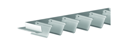
- Frame made from high quality aluminum profiled.
- Blades are sealed with foam gasket at the bottom to avoid rattling noise and to provide air fight operation.
- Blades open full or to any angle depending on the air velocity. Blades stay in position of opening without fluctuating when there is constant air flow. Blades close quietly when the air flow stops.
- Designed to maintain constant pressure level inside pressurized rooms by relieving excess air when it exceeds the desired limit.
- Generally installed on diesel generator plant rooms ventilation system and exhaust ducting.
- Non-return dampers prevent unwanted airflows against the intended airflow direction when the system is not in operation.
- Maximum differential pressure: 100 Pa.
- Casing with U-channel connection suitable for rectangular ducts.
- Available in standard sizes and many intermediate sizes.
- Non-return damper with formed aluminum blades for normal requirements; blades are fitted with seals for sound attenuation.
- Non-return damper, duct connection without flange holes.
- Non-return damper, duct connection with flange holes.
- Maintenance-free as construction and materials are not subject to wear.
- Contamination should be removed as it may lead to corrosion and to increased closed blade air leakage.

Technical Data
Application
- Non-return damper for Installation into ductwork.
- Prevention of unwanted airflows against the intended airflow direction when the system is not in operation.
- Blades close automatically when the system is shut down.
- Maximum differential pressure 100 Pa.
Special characteristics
- Any intermediate sizes within the standard size range are available.
- operating temperature: -20-80 °C.
- Maximum differential pressure: 100 Pa.
- Non-return dampers are opened and closed by the airflow; no actuator is required.
- Non-return damper with formed aluminum blades for normal requirements; blades are fitted with seals for sound attenuation.
Nominal sizes
■B: 200, 400, 600, 800, 1000, 1200, 1400, 1600 mm (intermediate sizes: 2011599 mm in increments of 1 mm).
■H: 215, 315, 415, 515, 615,715, 815, 1015, 1215, 1415, 1615 mm. (intermediate sizes: 216-1614 mm, in increments of 1 mm).
■Any combination of B x H.
Technical Data
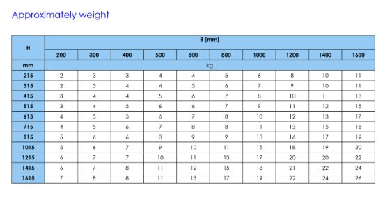
Dimensions and weight
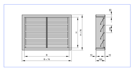
■B: 200-1600 mm, intermediate sizes 201-1599 mm in increments of 1 mm.
■H: 215-1615 mm, intermediate sizes 216-1614 mm in increments of 1 mm.
■The weight for the next larger size applies
Flow cross section to calculate the airflow velocity.
■A=BXH
Unit of measure for B and H: m.
Technical Data
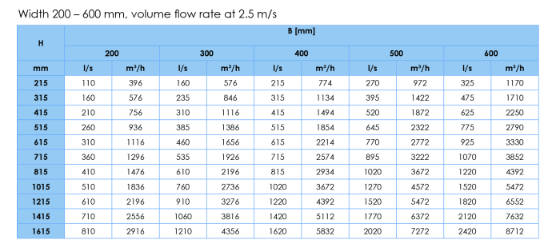
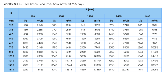
Quick sizing tables provide a good overview of the volume flow rates with an airflow velocity of 2.5 m/s. Intermediate values can be interpolated

Technical Data
Installation and commissioning
■Horizontal airflow: Vertical installation.
■Vertical airflow: Installation into ducts with an upward airflow; horizontal installation.
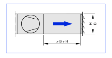
■Straight upstream section required (at least B H) on the positive pressure side of fans.
■ Ensure gradual start-up of fans to avoid Only for installation in internal spaces. sudden pressure increase.
■For external walls the damper should be combined with a Type WG-KUL external weather louver.
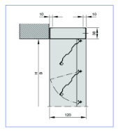
Installation into an internal wall, without installation sub frame
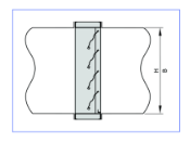
Duct installation
Installation on the discharge side of a fan
Performance Chart

How to order

