ALL DUCT LINE
| Duct Products
fire dampers
Fire Damper
A fire damper can be defined as “a device installed in ducts and air transfer opening of an air distribution or smoke control system designed to close automatically upon detection of heat.
It also serves to interrupt migratory airflow, resist the pas sage of flame, and maintain the integrity of the fire rated separation.”1 Its primary function is to prevent the passage of flame from one side of a fire-rated separation to the other.
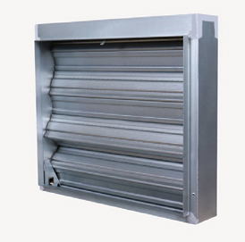
Fire dampers (Figure 1) are operated by a fusible device, typically a melting link. They are designed and tested under UL Standard 555: Standard for Safety for Fire Dampers, to maintain the integrity of the fire-rated separation. Fire dampers are equipped with a fusible link (rated for 165°F up to 286°F), which holds the blades open until it the link melts. Upon reaching the melting point, the blades then close and stop the flame from moving into an adjoining compartment
Location:
Fire dampers are installed in or near the wall or floor, at the point of duct penetration, to retain the integrity and fire rating of a wall or floor whether it is a ducted or open-plenum return application. Should the ductwork fall away, the damper needs to stay in the wall or floor to maintain the integrity of the wall or floor. One should actually think of the fire damper as part of the wall system itself.

Fire dampers are required to be installed in sleeves. Lighter gauge sleeves (18–20 ga.)require a breakaway connection from the sleeve to the ductwork. Heavier, smaller dampers (16 ga.) can be installed with a hard duct connection. The manufacturer’s installation instructions will include the ap proved method for attachment and spacing of the attachment (Figure 2).
The spaces between the damper frame and the duct typically are not sealed due to thermal expansion. Breakaway connections as well as other seams can be sealed if the manufacturer’s listing includes a UL-approved sealant.
There are two types of applications for fire dampers: static and dynamic. Static fire dampers can only be applied in HVAC systems that are designed to shut down in the event of a fire. Dynamic fire dampers have been tested for closure under airflow and carry both an airflow velocity (fpm) and pressure differential rating. The minimum rating for all dynamic fire dampers is 2,000 fpm and 4.0 in. wg. The mini mum ratings are based upon closure at a minimum airflow of 2,400 fpm and 4.5 in. wg.
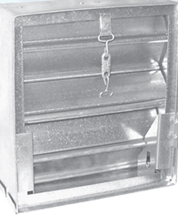
20 Ga (1mm) galvanized steel frame.
Blades :
24 Ga (0.7mm) interlocking type galvanized steel.
Fusible link :
U.L Listed standard F fusing temperature. (other temperatures available on request)
Mounting :
Vertical & horizontal mounting positions.
Fire rating :
1 1/2 hour rated for use in 1 hour or 2 hours partitions.
Springs :
Sealing :
side seals. . Finish. All steel parts with gal vanized mill finish.
Single section :
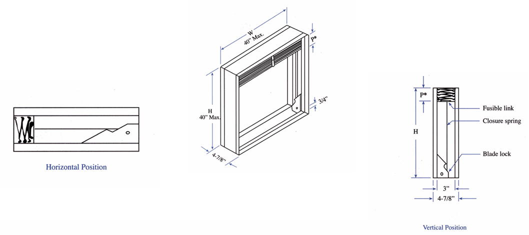
minimum size 6” x 6” W x H. Inch
maximum size 40” x 40” W x H. Inch.
Free area :
55-78% of Nominal
Recommended :
for low – medium air velocities.

Made from high quality galvanized steel gauge 16.
Stainless steel frame is
Blade :
Made from high quality galvanized steel
gauge 22.
Stainless steel blades are available as
option
Blade ramp:
Frome galvanized steel with aspring holder Closure spring
Made from stainless steel spring
Fusible links :
UL listed Fusible links which has fire rating
of 165oF / 212 oF

Installation
Sleeve
Made from galvanized steel gauge ( 16 – 10). Sleeve thickness must be thicker than duct connected to it. Sleeve gauge with the SMACNA duct connection fire, smoke and radiation damper installation HVAC systems and with NFPA-90A, damper must be secured inside sleeve by sub-frame and the sub frame to be fastened by steel rivets or bolt.
Made from galvanized steel gauge ( 16 – 10). Sleeve thickness must be thicker than duct connected to it. Sleeve gauge with the SMACNA duct connection fire, smoke and radiation damper installation HVAC systems and with NFPA-90A, damper must be secured inside sleeve by sub-frame and the sub frame to be fastened by steel rivets or bolt.

Performance data

Data Sheet
Construction and specifications :
Underwriters laboratory listed : yes.
Loading :
Minimum: 1 Ibs
Maximum : 10 Ibs
Size :
Length :1.500 inches
Width : .562 inches
Distance between centers : .930 inches
Material :
Stamping :steel
Solder : bismuth alloy
Unit weight : .16 Ibs
Available with long or short hooks : yes
For specific fusible link ratings.
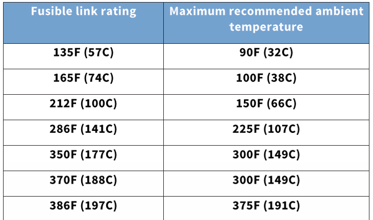
Many other temperature available ( non – UL listed )
Numbers derived from underwriters laboratories standard UL 33
ELSIE MFG CO INC
600 W MAPLE ST
PO BOX 97
WATERLOO, IN 46793 USA
Issue A, in the 135, 165, 212, 225, 350, 360, 370, 386°F temperature ratings. For loads from 1 to 30 lbs incl Bearing length 2 in.
Issue AM, in the 165°F temperature rating. For loads from 1 to 30 bs. incl. Bearing length 2 in. Issue B, in the 135, 165, 212, 286, 350, 375°F temperature ratings. For loads from 1 to 10 lbs incl Bearing length 1-3/16 in.
Issue C, in the 165, 212, 370°F temperature ratings. For loads from 2 to 50 lbs incl. Bearing length 3-3/8 in.
Issue D, in the 165, 212, 285, 286°F temperature ratings. For loads from 1 to 40 lbs incl. Bearing length 2 in.
Issue E, in the 165, 212, 286, 350, 360°F temperature ratings. For loads from 2 to 50 lbs incl Bearing length 1-1/4 in.
Issue GFC housing frame, in the 165, 212°F temperature ratings. For loads from 4 to 40 bs inel. Issue Y, in the 165, 212°F temperature ratings. For loads from 1.25 to 40 lbs incl.
Last Updated on 2008-11-20
©2013 UL LLC
When the UL Leaf Mark is on the product, or when the word “Environment” is included in the UL Mark, please search the UL Environment database for additional information regarding this product’s certification.
The appearance of a company’s name or product in this database does not in itself assure that products so identified have been manufactured under UL’s Follow-Up Service. Only those products bearing the UL Mark should be considered to be Certified and covered under UL’s Follow-Up Service. Always look for the Mark on the product.
UL permits the reproduction of the material contained in the Online Certification Directory subject to the following conditions: 1. The Guide Information, Assembles, Constructions, Designs, Systems, and/or Certifications (files) must be presented in their entirety and in a non-misleading manner, without any manipulation of the data (or drawings). 2. The statement “Reprinted from the Online Certifications Directory with permission from UL” must appear adjacent to the extracted material. In addition, the reprinted material must include a copyright notice in the following format:
“©2013 UL LLC”.
R4059
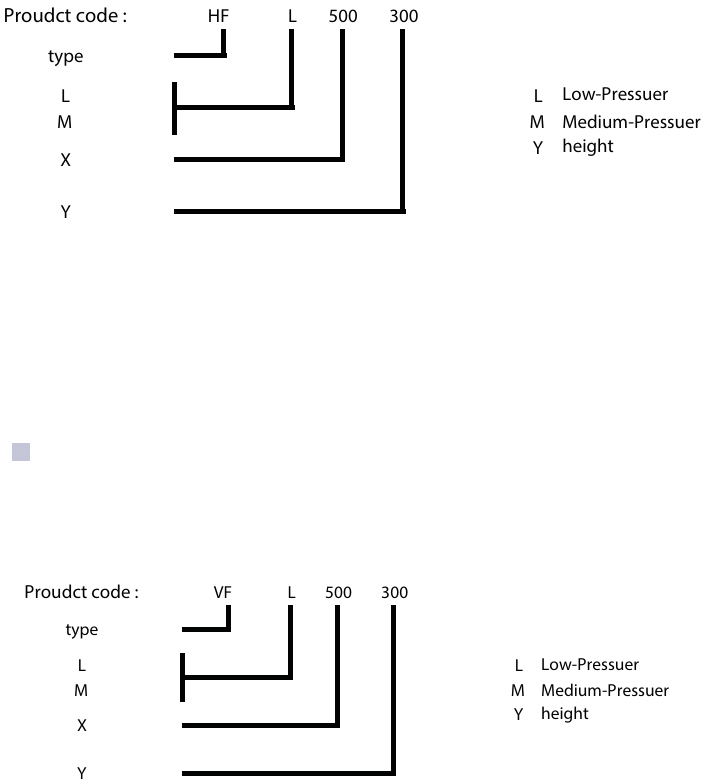
How To Order
