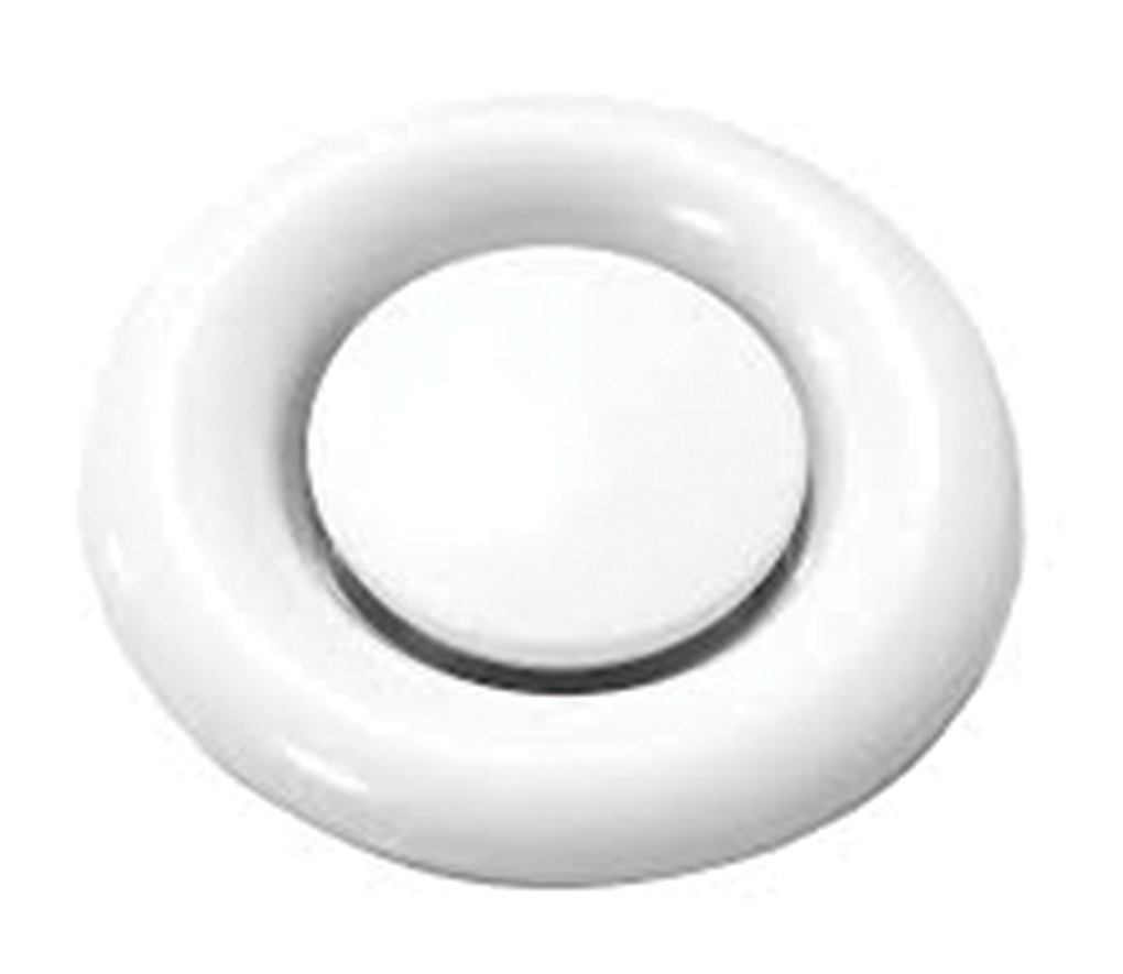
Disc Valves DV
Construction

Steel sheet construction.
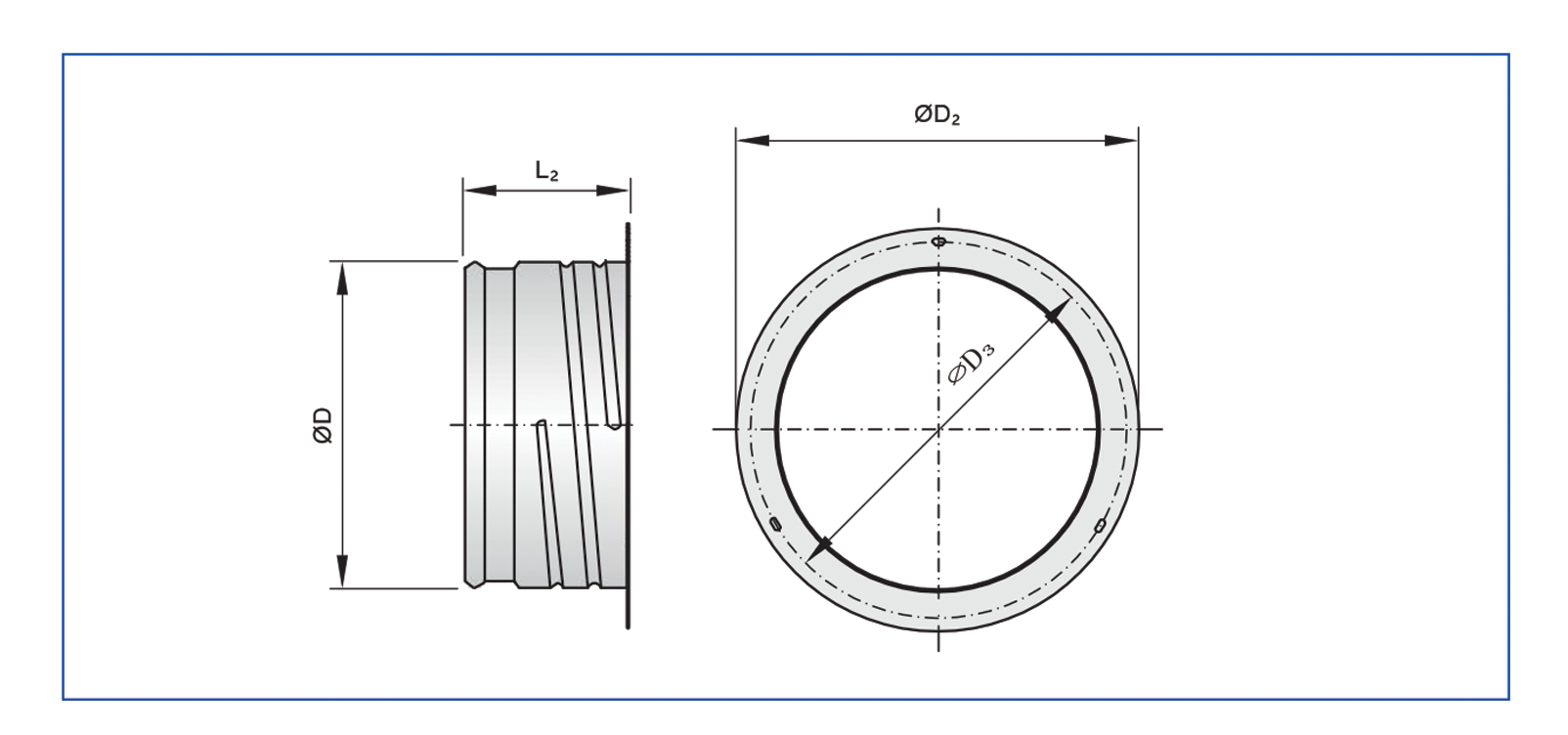
2- Mounting rings
Galvanized sheet steel.
① Valve disc
② Valve casing
③ Cross bar
④ Threaded spindle with lock nut

Description
- Frame and disc is made of high quality galvanized steel sheet construction with powder coating to RAL colors.
- Disc is attached to the frame by threaded rod.
- Air flow can be adjusted by regulating the cone up or down (+A or -A).
- Foam gasket is sealed around the back of the frame to avoid air leakage.
- These valves can be used for supply, exhaust and ventilation applications.
- Air master disc valves are best suited to air distribution systems handling relatively low air flow rates within small circular duct work.
- Can be mounted in wall, ceiling or exposed air ducts with mounting rings.
- Recommended for exhaust of greasy and damp air in damp areas such as toilets, bathrooms and kitchens.
Standard finishes
- Steel sheet powder coated to RAL 9010 color.
- Flexibility of finishing is available as option.
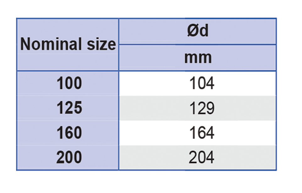
Standard sizes :

Fixing details
- Direct fixing into the duct with mounting rings.
- First mounting ring has to be fixed into the duct outlet before the valve is pushed into the ring.

Technical Data
- Type DV disc valves are used as extract air devices in small rooms.
- For variable and constant volume flows.
- For walls and suspended ceilings.
Special characteristics
- Continuous volume flow rate balancing by turning the valve disc.
- Easy to install.
Nominal sizes
- 100, 125, 160, 200.
Parts and characteristics
- Valve disc with threaded spindle and lock nut.
- Valve casing including cross bar with orifice for the threaded spindle.
- Installation sub frame that accommodates the disc valve.
Materials and surfaces
- Valve casing and valve disc made of galvanized sheet steel.
- Installation sub frame, cross bar, threaded spindle and lock nut made of galvanized steel.
- Foam seal.
- Valve casing and valve disc powder-coated RAL 9010, pure white.
Standards and guidelines
- Sound power level of the air-regenerated noise measured according to EN ISO 5135.
Maintenance
- Maintenance-free as construction and materials are not subject to wear.
- Inspection and cleaning to VDI 6022.
Technical Data
Table 9.2(A) Air flow data Supply air disc valve

Pt = Total pressure loss across the disc valve in mm of H2O.
NC based on a room attenuation of 10 dB
A = +10,0 & -10 = Position of the disc 10 mm down of normal position, at normal position, and 10 mm above normal posits
Technical Data
Table 9.2(B) Air flow data Return air disc valve

Pt = Total pressure loss across the disc valve in mm of H2O.
NC based on a room attenuation of 10 dB.
A = +10,0 & -10 = Position of the disc 10 mm down of normal position, at normal position, and 10 mm above normal position.
Technical Data
- Quick Sizing tables provide a good overview of the volume flow rates and corresponding sound power levels and differential pressures.
- DV/100, DV /125, sound power level and total differential pressure

- DV /160, sound power level and total differential pressure

- DV /200, sound power level and total differential pressure

Sizing example
Given data
- V = 25 l/s (90 m3/h)
- Extract air valve
- Maximum sound power level 30 dB(A)
Quick sizing
- Type DV
- Selectable nominal sizes: 125, 160, 200
- Selected: DV/125
Technical Data
DV

Installation sub frame for DV and Z-DV


Technical Data
Installation and commissioning
- Installation flush with the wall or ceiling.
- Perform volume flow rate balancing by turning the valve disc, then tighten the lock nut to fix the valve disc in the required position.
- These are only schematic diagrams to illustrate installation details.
Installation flush with the wall or ceiling, with installation sub frame

Installation opening

Performance Data
Table 9.1 Supply air valves Vs Throw in meters (A = 0)

Note
For position A = +10, reduce throw by 30%.
For position A=-10, increase throw by 40%.
How to order

